SPA-RV
real-time disturbance event reporting system
26 January 2021
Timely detection and recording of developing faults and disturbances, together with structured, accurate and complete analysis of incoming disturbance data, are essential for prompt operational decisions, root cause analysis and prevention of future incidents.
Thousands of digital fault recorders are installed across Russia's Unified Energy System, collectively generating hundreds or thousands of waveform records every day. Many records relate to routine equipment switching, disturbances at neighboring facilities, successful automatic reclosing and similar events. Most such records are of limited interest to operating personnel.
Collecting and analyzing all waveform records manually is labor-intensive and slow, and introduces the risk of human error when selecting and evaluating information.
Existing automated disturbance data collection systems generally transfer all data indiscriminately from recorders and, at best, place the files in a basic database organized by time.
System functions
SVEY specialists have developed an intelligent automated system for collecting and analyzing disturbance files from AURA recorders. It provides:- Automatic real-time retrieval of disturbance recordings from recorders over IEC 60870-5-104, with the volume of transmitted information hundreds of times smaller than the full disturbance file.
-
Automatic analysis of received disturbance records and generation of text event reports, including:
- fault occurrence and fault type;
- single-ended and double-ended fault location;
- protection operations;
- the reasons for protection operation;
- assessment of correct protection operation.
- Notifications of events that require attention.
- Display of records for further analysis, including waveform plots and phasor diagrams.
- Storage of disturbance parameters in a database for each recording channel, making it straightforward to analyze events captured by several recorders.
- Storage of text messages in the database, linked to the relevant disturbance record.
- Automatic retrieval and database storage of the original disturbance file recorded by the device.
- Data storage for compiling disturbance statistics over a selected period, including recorder triggers, fault trips and circuit-breaker duty.
- As an additional function, the system can receive normal operating measurements through spontaneous transmission and store them in the database.
System architecture
The SPA-RV architecture closely follows the SCADA architectures widely used at power supply facilities. digital fault recorders send information spontaneously over digital communications links to the SPA-RV server using IEC 60870-5-104. The server stores the data in its database and forwards it to user workstations and higher-level servers.
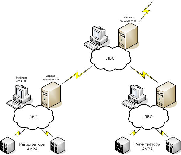
System operating sequence
- One or more recorders are triggered.
- The disturbance record is transmitted over IEC 60870-5-104 to the nearest server in the system hierarchy. Timestamped channel samples are transmitted spontaneously and stored in the server database.
- The disturbance is analyzed automatically, producing an account of equipment operation and locating the fault. When recorders at both line ends are triggered, double-ended measurements are used for fault location, significantly improving accuracy.
- The generated text report is stored in the database.
-
Operating personnel are notified of the disturbance through a link to the text report. A red icon flashes in the lower-right corner of the taskbar until an operator acknowledges it.

Disturbance notification - Retrieval of original disturbance files from recorders and storage in the database. Where low communication speeds make large files difficult to transfer, files can be delivered by any available method and imported manually.
- Where no communications link is available, a dedicated server software option imports the files into the database, converts them to IEC 60870-5-104 format and generates a text report.
-
Historical records can be viewed using any selection of channels from any number of recorders. All quantities required for detailed analysis are available:
- RMS analog signal values before, during and after a fault;
- phase relationships of sinusoidal analog signals before, during and after a fault;
- frequency of sinusoidal analog signals before, during and after a fault;
- the time of each signal measurement;
- binary signal states and the times of their changes.
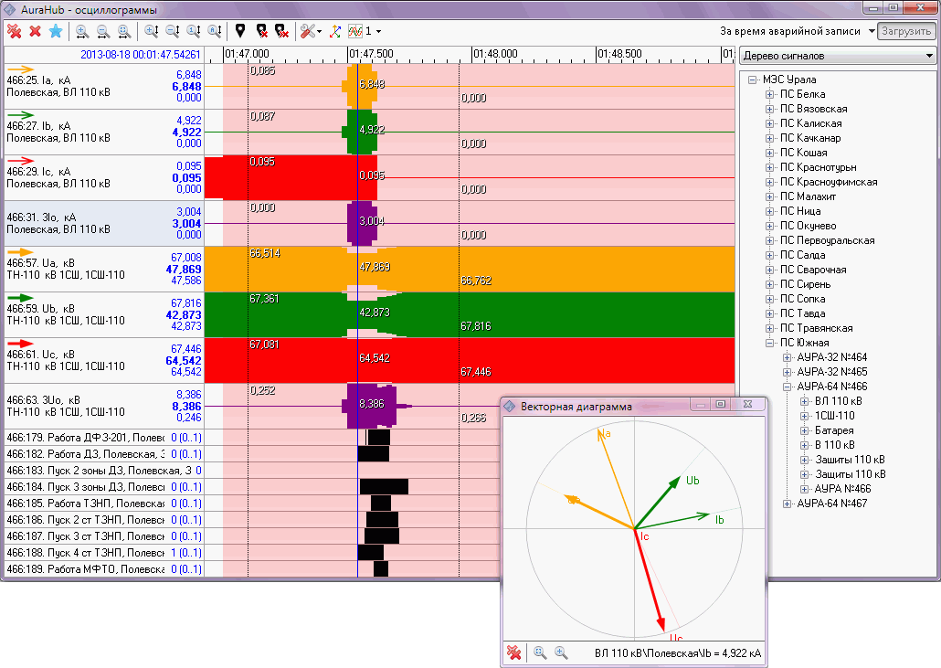
Disturbance records are therefore processed within seconds.
Software description
1.26 MB