
AURA-08-R


Distributed Digital Fault Recorder (DFR)
- up to 256 analog and 1,024 binary channels
- modular design with quick replacement of individual modules
- support for distributed transducers
- digitized data transfer from transducers over the AURA-R network
- additional binary signals received digitally over IEC 61850
- the recording unit runs AURA Linux and AuraQt
- recorder software listed in the Russian Software Register
- approved by PJSC Rosseti for use at facilities operated by its subsidiaries and affiliates
- has measuring instrument type approval
- is listed in the Russian registers of industrial and electronic products
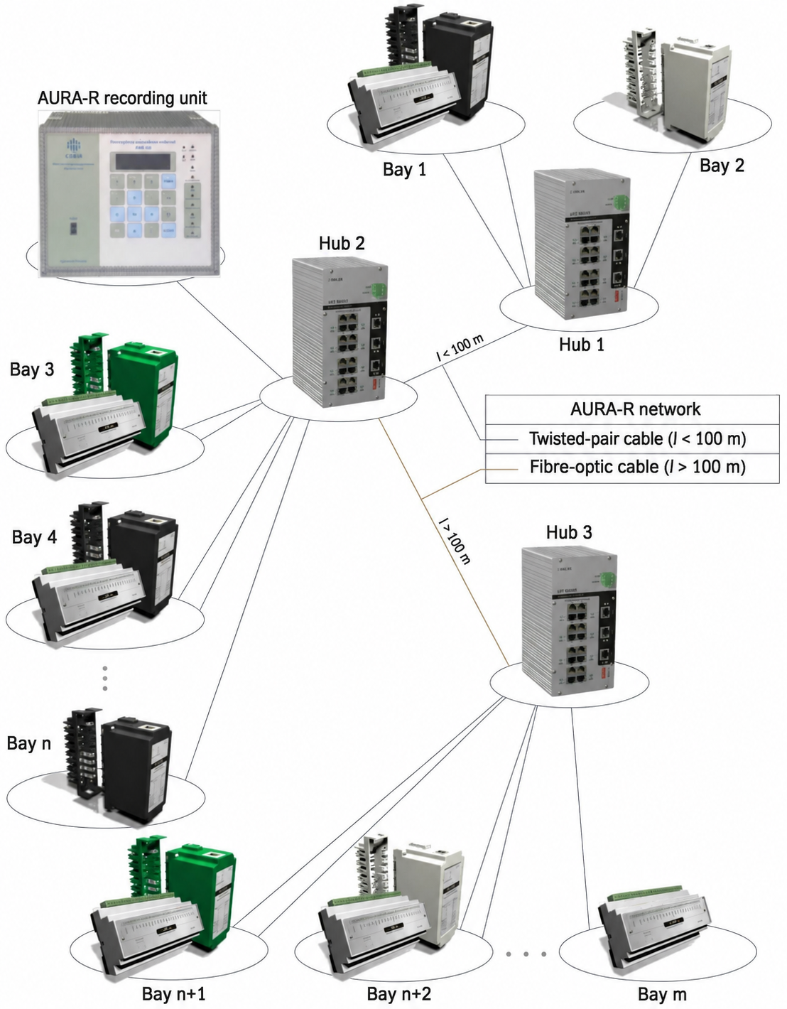
The AURA-08-R recorder backbone comprises central-unit-to-concentrator and concentrator-to-concentrator segments. Peripheral segments connect input transducers to the concentrators. Up to 8 concentrators are supported. Each concentrator polls 8 analog signal transducers and 8 binary input modules. Components are connected using Category 5 or higher UTP cable. Backbone segments longer than 100 m use fiber-optic cable.
Request a quoteThe AURA-08-R digital fault recorder comprises separate functional modules operating on a dedicated local network, AURA-R. Its backbone consists of the following links.
- central unit to concentrator,
- concentrator to concentrator,
The backbone carries all system data. Peripheral links connect the following devices.
- concentrator to analog signal transducer,
- concentrator to binary input module,
These links carry measurement data into the network. The AURA-R network uses Ethernet physical-layer technology.
Concentrators have one input and two output ports for connection to the recorder backbone, allowing the network to branch. Up to 8 concentrators are supported. Each concentrator polls 8 analog signal transducers and 8 binary input modules. Components are connected using Category 5 or higher UTP cable. Backbone segments longer than 100 m use fiber-optic cable.
Digital data from the input transducers reaches the recording unit in real time and is saved to storage when the recorder is triggered.
Design
The functional modules have aluminum extrusion housings that provide electromagnetic shielding and the mechanical strength required for long-term industrial operation.
Applications
automated monitoring and control systems for equipment at power and industrial facilities.
The distributed recorder is particularly suitable for large sites, where its architecture reduces cabling from primary sensors and simplifies installation.
The recorder main unit can be installed a considerable distance from the monitored equipment, making it suitable for sites at risk of catastrophic damage, such as hydroelectric and nuclear power plants.
The recorder has no intermediate data storage points. All data is sent directly to the central unit, so disturbance information is retained if the system's primary components are destroyed.

The AURA-08-R central unit has a metal housing made from an aluminum extrusion.
The main unit contains a processor board, an AURA-R concentrator network interface board, a keypad and display unit, and an alarm board.
Ethernet interfaces provide external communication. USB ports allow recorded disturbance files to be copied to a USB drive, and a COM port is available for connecting a precision time receiver.
The main unit has a fanless, dust-protected enclosure. It is powered by an external 24 V DC power supply accepting 120–370 V DC or 85–264 V AC. Two power supplies can be fitted on request for redundancy, including operation from two independent supplies.
The front panel of the main unit contains:- LED indicators and a character display;
- buttons for viewing status, triggering a test recording and resetting alarms.
- connectors for AURA-R network concentrators;
- the recorder power button;
- a connector for the 24 V DC power supply;
- terminal block for external alarm circuits;
- Ethernet ports;
- processor board connectors for external devices
Operating system: AURA Linux, listed in the Russian Software Register.
Concentrators form the AURA-08-R recorder backbone and connect peripheral links to analog signal transducers and binary input modules.
The ADDRESS KR switches determine which recorder database channels correspond to measurements received from each concentrator.
Concentrator port assignments:- Port “A” connects PRN, PRT, PRPN and PRPT analog signal transducers;
- Port “D” connects DS binary acquisition modules;
- The bidirectional KR port connects concentrators to one another or to the AURA-08-R recording unit.
| Concentrator type | Number of AURA-R network ports | |
|---|---|---|
| KR-8800 | Eight “A” ports and eight “D” ports. | 3 KR ports. Twisted pair. |
KR-8800 | ||||_____ “KR” port type | || 00 — twisted pair | ||_______ number of “D” ports | |________ number of “A” ports |___________ device typeThe concentrator front panel contains:
- a 24 V DC power connector;
- KR1, KR2 and KR3 connectors connect the concentrator to the AURA-08-R recorder backbone;
- six network address setting switches for the concentrator;
- A and D connectors for analog transducers and binary input modules.

Input transducers
AURA-R transducers use standardized plug-in plastic enclosures, with four channels per enclosure. Four screws secure the cover to the connector section, and two latches lock the transducer into the mating connector. The input connector follows the design of conventional BI-6 test blocks: removing a transducer shorts the current circuits and allows current injection and insulation testing of the incoming cables. Guide projections between the connector blades prevent accidental short circuits if the transducer is misaligned during insertion. The mating connector has M4 screw terminals for input and output circuits. Different transducer types have different enclosure colors, with matching mating connectors.
Four-channel analog transducers digitize their input signals with a 16-bit ADC and send instantaneous samples in response to concentrator requests. The data port carries digital communications with the concentrator and also supplies power to the transducer.
The three types of analog transducer use the same housing and differ externally only in housing color and front-panel markings.
tr>| Part number | ||||
|---|---|---|---|---|
| Name | Specifications | |||
| AC voltage transducer | ||||
| TVGTs.03.2209-250V | PRN-250 | ranges: 250 V, 160 V, 120 V, 80 V | ||
| AC current transducer | ||||
| TVGTs.03.2609-20A | PRT-20 | ranges: 2 A, 4 A, 10 A, 20 A | ||
| TVGTs.03.2609-200A | PRT-200 | ranges 200 A, 100 A, 40 A, 20 A | ||
| DC voltage transducer | ||||
| TVGTs.03.2909-24V | PRPN-24 | ranges: 24 V DC / 20 V AC | ||
| TVGTs.03.2909-330V | PRPN-330 | ranges 330 V DC / 250 V AC | ||
| TVGTs.03.2909-600V | PRPN-600 | ranges: 600 V DC / 600 V AC | ||
| DC current transducer | ||||
| TVGTs.03.2709-20mA | PRPT-0.02 | ranges: 20 mA DC / 20 mA AC | ||
| TVGTs.03.2709-200mA | PRPT-0.2 | ranges 200 mA DC / 200 mA AC | ||
| TVGTs.03.2909-0.2V | PRPN-0.2 | ranges 0.2 V DC / 0.15 V AC | ||
Binary input unit
The DS-16 binary acquisition module has a detachable terminal block for 16 volt-free contact inputs and a rear DIN-rail mounting clip.
The LED glows green when the transducer is connected to the recorder network and exchanging data.

DS-16
MK-01 media converter
The media converter converts electrical signals to optical signals and vice versa.
Two media converters can connect one remote analog transducer or DS binary input unit more than 100 m from the concentrator.
The media converter requires 24 V DC. An external 24 V, 10 W DIN-rail power supply is available as an option.

| Cable type | Connector type | Description | Communication distance |
|---|---|---|---|
| Cat. 5 (5e) UTP | RJ-45 | Twisted pair | 100 m |
| STP | Shielded RJ-45 | Shielded twisted pair | 80 m |
| Duplex single-mode optical fiber | Dual SC connectors: Rx (SC) and Tx (SC) | Wavelength 1310 ±50 nm | 2,000 m |
- ADC resolution: 16 bits
- Triggers: any analog or binary channel, calculated channels, including U2(I2) and 3U0(3I0)
- Cabinet supply 220/110 V DC, 220/127 V AC
- Binary alarm output specifications:
- Switching voltage up to 400 V
- Switching current up to 100 mA
- Storage: flash drive, 240 GB minimum.
- Communication: 10/100/1000 Mbps Ethernet
- Operating temperature range: +1 to +45 °C
- Climatic category: UHL4 or O4 under the Russian classification
The recorder complies with GOST R 58601-2019.
AURA-08 recorders are listed in the Russian State Register of Measuring Instruments, registration no. 90938-23.
Accuracy class:
AC current and voltage: 0.5%
DC current and voltage — 0.5%
phase displacement: 1 degree
frequency — 0.05 Hz


- ADC resolution: 16 bits;
- Measurement error no greater than 0.5%;
- Galvanic isolation voltage: 3000 V;
- Input impedance at 50 Hz:
- AC current transducers: 0.0075 Ω;
- AC voltage transducers: 2 kΩ;
- DC voltage transducer input current — 0.5 mA.


- recording AC and DC voltage and current signals by capturing instantaneous values and digitizing them as a sequence of amplitude- and time-quantized samples at the configured sampling rate;
- calculating RMS values, mean values and symmetrical components of analog signals by digitally processing the recorded samples;
- determining the fundamental frequency of the recorded AC current and voltage signals;
- recording binary signal states;
- saving recorded values and their associated attributes, including timestamps, channel names, transformer ratios and sampling rate, in IEEE Std C37.111 COMTRADE 2013 format;
- providing secure remote access to recorder data;
- capturing network traffic while recording disturbance waveforms. Captured traffic is saved to a *.pcap file for viewing and analysis in suitable software such as Wireshark. A built-in traffic analyzer is available from AuraQt v1.2.0.0;
Data storage and transfer
Disturbance files remain in the recorder's nonvolatile memory until deleted.
Files can be deleted in the following ways.- manually;
- automatically after a new recording, by deleting the oldest file when disk usage reaches 80%;
- On a large drive, the number of files can reach several thousand, making them harder to manage. The recorder allows a maximum file count to be set. When a new recording exceeds this limit, the oldest excess file is deleted automatically.
- by connecting a laptop to the recorder's Ethernet interface. A standard web browser such as Google Chrome provides access. Connections are secured with digital certificates. Access permissions can be assigned according to the user privileges specified in the certificate.
- By copying files directly from the recorder to a USB flash drive. When a drive is inserted into the recorder’s USB port, recent disturbance files that have not yet been copied are copied automatically, together with a transfer report. Individual files can also be selected and copied using the main unit keypad.
- downloading files directly through the web interface using a standard browser such as Google Chrome. Connections are secured with digital certificates. Access permissions can be assigned according to the user privileges specified in the certificate;
- automatically sending data to specified servers over FTP(S), SFTP or IEC 61850-8-1 MMS.
-
IEC 60870-5-104 and IEC 61850-8-1 MMS.
-
No. RU C-RU.AB03.N.00013/23 678 KB
-
EAEU No. RU D-RU.RA01.V.71292/19 471 KB
-
Operating manual, Part 1
14.06.2024ТВГЦ.411733.003 РЭ часть 1.pdf 1.9 MB -
Operating manual, Part 2
16.09.2026TVGTs.411733.003 Operating Manual, Part 2.pdf 15 MB -
Workstation setup guide for AuraQt software
29.01.2024TVGTs.411733.003 Operating Manual, Part 2.pdf 770 KB -
Operator manual (AuraQt software)
09.11.2023AuraQt.pdf 6.2 MB -
AURA order specification form
15.04.202648 KB -
AURA-08 measuring instrument type approval certificate.pdf 602 KB